 LT-1900
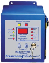
The LT-1900 is a time-based stopping performance monitor that utilizes a high resolution linear transducer and controller to measure the machine stopping time in milliseconds and also the SPM of the press. The linear transducer is attached to the subject machine and is driven on a 1:1 linear ratio by the machine. The machine stopping time of the machine will be displayed on every stop and can be easily read on the bright red light emitting diode (LED) display on the front panel of the unit. The SPM of the machine will be displayed during the machine cycle.
Warning Indicator Failure Indicator The LT-1900 is a time based stopping performance monitor that utilizes a high resolution linear transducer and controller to measure the machine stopping time in milliseconds and also the SPM of the machine. The linear transducer is attached to the subject machine and is driven on a 1:1 linear OSHA/ANSI Compliance • Control reliable design Controller Power Consumption – 8 watts (Relays on) Temperature Range – 0º to 50º Celsius Relay Configuration – Dual self-checking force-guided captive contact safety relays Relay Contact Rating System Accuracy – +/- 1 millisecond Setpoints – Drive Failure (1 to 25 tenths of a second) Enclosure – NEMA 12 (IP 64) Steel Front Panel Mount – 8” (203mm) Height x 7” (178mm) Width x 4” (102mm) Depth Indicators: Enclosure rating: NEMA 12, IP 64 Mounting Brackets – Supplied standard with each linear transducer 1. Specify Mounting Style 2. Specify Controller input power 3. Specify Hydraulic Valve Coil Voltage 4. Specify linear transducer length (must equal or exceed maximum machine stroke length) 11-001 Metal box enclosure (with gasket) (NEMA 12, IP 64) 15-079 8 position mini-Euro plug connector (Linear Sensor) 26-101 Front panel overlay (LT-1900) 32-101 Safety relay (4 pole, 12 VDC, clear) 42-001 Software microprocessor chip (specify square or rectangular) 52-002 Display board 40-009 4” (10.7” – 272mm total length, 4.3” – 110mm sensor area) linear transducer with 40’ (12m) cable
Yellow light illuminates when the setpoint is exceeded. Excellent input for the machine operator and for maintenance.
Motion Failure
Red LED illuminates when the pulses from the failure disappear.
Stopped/No Motion
Yellow LED illuminates when power to the valve drops out.
Ready
Green LED illuminates when all systems are go.
Not Ready
Red LED illuminates when the monitor safety relays have dropped out (i.e., drive failure, internal failure, etc.)
+/- Pushbuttons
The +/- pushbuttons are used to set the time values in milliseconds for the stopping performance warning and the limit setpoints.
Red LED illuminates when the actual stopping time exceeds the programmed stop limit setpoint.
Stop Time
Displayed in milliseconds after every stop in machine cycle and the red LED is illuminated.
SPM
Displayed during each machine cycle when the red LED is illuminated.
Stopping Performance Warning Time
Displayed in milliseconds when the red LED is illuminated.
Stopping Performance Limit Time
Setpoint is displayed in milliseconds when the red LED is illuminated.
System Programming Security and Safety
Keyed selector switch controls:
• Warning Time Setpoint
• Limit Time Setpoint
• System Reset
• System Run
ratio by the machine. The stopping time of the machine will be displayed on every stop and can be easily read on the bright red light emitting diode (LED) display on the front panel of the unit. The SPM of the machine will be displayed during the machine cycle.
Individual LED indicators are visible and easily define the existing status of the unit during the machine cycle (shown above). All system programming and diagnostics are front panel mounted and controlled which will minimize downtime while enhancing operator safety and machine maintenance. All operating mode selections are supervisory controlled by a keyed selector switch which meets all OSHA and ANSI standards for mode selection supervisory control.
To program the Warning Time and the Limit Time setpoints, the user inserts the programming key into the lock and turns to the desired position (status LED illuminates). By depressing the +/- buttons to the desired time setting and turning the key back to the Run position, the new warning/failure time setpoints are saved. All errors and time value setpoints are permanently stored in the EEPROM memory which does not require a battery backup. The user cannot change or reprogram the Warning or Limit
setpoints while the machine is in motion, which is an additional safety feature.
The dual force-guided captive contact safety output relays of the LT-1900 are always de-energized when the programming key is not in the Run position. When the key is in the Run position, the safety output relays are always energized as long as there are no internal or external faults detected. When a fault is detected, it is recorded within the system in non-volatile memory along with the last stopping time. If the power to the LT-1900 Monitor System is removed and reapplied, the last error to occur will come back up and prevent any further use until the programming key is used. Only the key turned to the reset position can clear a fault. If no fault occurred but the programming key is moved into the reset position, the output relays will de-energize as a safety feature. Motion detection will still be monitored while in the Reset position even if the linear transducer has motion.
The LT-1900 system complies with OSHA code 29 CFR 1910.217 and ANSI Codes B11.3-2012 and
B11.2-2013 for monitoring and control reliability standards. The unit will automatically prevent the activation of a successive stroke if the stopping time deteriorates beyond the brake limit setpoint.
Non-volatile EEPROM Memory
All diagnostic faults and setpoints are permanently saved in non-volatile memory which does not require battery backup. Information is retained indefinitely after a power loss or machine shutdown.
Advanced Design
The advanced circuitry and user friendly design on the LT-1900 allows both programming and status monitoring to be performed from the front of the compact panel. There is no need to enter the control panel to adjust switches or thumbwheels which will enhance both safety and productivity.
System Self Diagnostics
Control displays status and system fault codes are on the LED display. A detailed definition, cause, and cure listing is supplied within each installation and operation manual.
Predictive Maintenance Diagnostic Tool
The unique “warning” feature on the LT-1900 allows for predictive maintenance to be scheduled on the machine, which will minimize downtime. Factors which will be monitored and affect stopping time: machine cycle speed, air supply, tooling weight, exhaust restrictions, wear adjustment and pressure.
Stop Time Measurement Built-In
The built-in stop feature initiates a stop signal in the downstroke. This is required information when calculating the location of point of operation guarding systems or operator palm button assemblies.
Complete Package Supplied
Everything you need to install and operate the LT-1900 is supplied.
• LT-1900 Controller
• Linear Transducer and Brackets
• Magnet
• 40′ (12m) of transducer cable
• Dimensional and technical data
• Installation and operation manual
• Dual captive contact safety relays
• Bright red LED display
• Non-volatile EEPROM memory
• Flat unobtrusive design
• Drive failure detection
• Motion detector
• Automatic 90º and stop time tester press stop
• Programming security with keyed selector switch
• Very easy to program and to adjust limits
• System self-diagnostics with display codes
• External diagnostic display
• System status indicators (LED’s)
• Solid state indicators – No incandescent bulbs to burn out
• Designed specifically for the rigorous metal stamping/metal forming industry
• Interfaces easily with all types of machine controls; solid state or relay logic
• Installs with ease on OEM, retrofit, or rebuild projects
• Front panel mount for installation into an existing control panel
• Made in USA
Power Requirements – 120 +/- 10% VAC, 50-60 Hz
24 VDC +/- 10% (optional)
8 amps @ 250VAC resistive for safety relays
4 amps @ 250VAC resistive for alarm relay
Warning (1 to 999 milliseconds)
Failure (1 to 999 milliseconds)
Fault – Red LED
Warning – Yellow LED
Motion Fault – Red LED
Stopped/No Motion – Yellow LED
Ready – Green LED
Not Ready – Red LED
Stop Time Display – Red LED
SPM – Red LED
Warning Setpoint – Red LED
Limit Setpoint – Red LED
Dimensions – .34” (8mm) high, 1.1” (28mm) wide (all lengths)
Active Length – 4” (101mm) active zone – 10.3” (263mm) total length
Active Length – 8” (203mm) active zone – 14.7” (365mm) total length
Active Length – 12” (305mm) active zone – 18.4” (467mm) total length
Active Length – 16” (406mm) active zone – 22.3” (568mm) total length
Active Length – 24” (609mm) active zone – 30.4” (771mm) total length
Cable Length – 40’ (12m) supplied standard with each linear transducer
F ……… Front Panel Mounting to be installed in an existing control panel.
C ……… Stand alone NEMA12 (IP 64) steel enclosure.
1 ………. 24VDC
2 ………. 120VAC 50-60Hz
1 ………. 24VDC
2 ………. 120VAC 50-60Hz
04 ………. 4” (101mm) active length
08 ………. 8” (203mm) active length
12 ………. 12” (305mm) active length
16 ………. 16” (406mm) active length
24 ………. 24” (609mm) active length
*Over 24” (609mm) stroke required. Consult factory.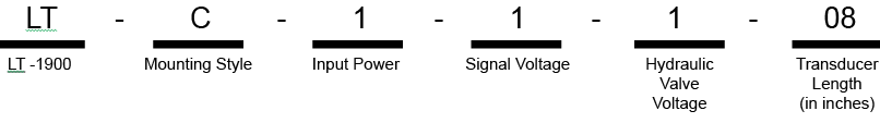
11-073 Metal panel mount (with gasket) open frame for LT-1900
20-001 1A Slo-Blo glass 3AG fuse
20-022 1A Slo-Blo nano SMF fuse
52-084 Ribbon Cable
52-202 Transducer board
52-319 Computer / Power supply / Relay board (with CPU)
40-010 8” (14.7” – 372mm total length, 8.3” – 210mm sensor area) linear transducer with 40’ (12m) cable
40-011 12” (18.4” – 467mm total length, 12” – 305mm sensor area) linear transducer with 40’ (12m) cable
40-012 16” (22.5” – 572mm total length, 16.1” – 410mm sensor area) linear transducer with 40’ (12m) cable
40-013 24” (30.4” – 772mm total length, 24.0” – 610mm sensor area) linear transducer with 40’ (12m) cable
40-014 LT-1900 sensor Magnet (requires 1)
40-015 LT-1900 Sensor Mounting Bracket (requires 2)